This article is about how to burn bootloader to Atmega328 on a breadboard.
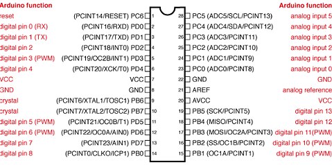
Atmega328 pin definition
Components needed
- 1 x 10K 1/8 watt resistor.
- 2 x 22pF capacitors.
- 1 x 16 MHz crystal.
- 1 x Breadboard.
- hookup wire.
Wiring up the breadboard
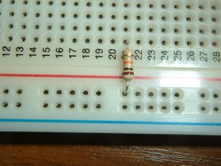
Begin by inserting a 10K resistor from the breadboard's 5 volt bus at about row 21, as shown here.
This will mark the ATMega328's Pin 1 - its RESET pin. Pulling this pin high (ie to +5 volts) through the 10K resistor will stop any uncertainty about the pin's "state" and will prevent it resetting the chip at an inconvenient moment.
The resistor is also a useful "reference point" for when we insert the other few components we need to build the minimal Arduino clone.

Now that we know where the ATmega328's pin 1 will be, we can add the chip's +5 volts and ground connections.
The main +5 volts is on pin 7. Since we inserted the 10K resistor for pin 1 at the breadboard's row 21, it's easy to work out that the +5 volt pin will be at breadboard row 27. Next door, at pin 8, we can insert the chip's ground connection.
Looking at the ATMega328's pinout drawing above, we can see that there's another ground connection on the other side of the chip, directly opposite pin 7. So, we can easily pinpoint that location and add a ground wire.
On the same side, there are two more power connections (for the Analogue funtions in the chip). We can just tie those to the +5 volt bus for now.
And finally, as we've used both edges of the breadboard's power buses, we need to join them together - the two long vertical wires in this picture.
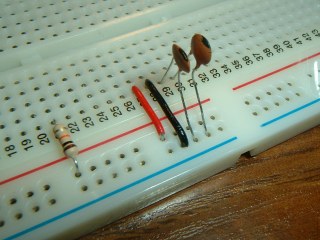
Next we need to insert the two 22pF capacitors between the two Crystal Oscillator pins on the ATmega328 and the breadboard's Ground bus - as shown here.
The ATmega328's crystal oscillator pins are pins 9 and 10. Nice and easy to locate right alongside the ground connection at pin 8.
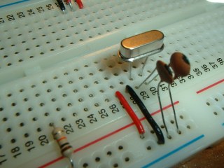
The last component to go in, before the chip itself, is the 16MHz crystal. The pin-spacing on crystals is usually wider than across two rows on the breadboard so you'll need to bend them inwards slightly. Make sure the crystal case isn't touching a lead of either of the capacitors.
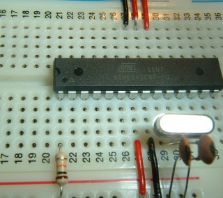
And finally, the ATmega328. Pin 1 is aligned with our 10K resistor on breadboard row 21. It sits across the trough in the breadboard and everything else falls into place!
The breadboard will get its power from the Arduino that's going to be doing the programming, so connecting the Arduino to the breadboard is the next step (nearly!).....
Luckily for me, someone a lot cleverer than I am has done all the work here. Bill Westfield ("WestfW") has written an Arduino sketch which not only has all the code required to do the burning, it contains text "images" of a bootloader version he calls "OptiLoader" - actually several images for the various flavours of ATMEL chips (328, 328-P, 168 and 8).
To make sure you get the latest versions, I'll simply post a link here: Bill Westfield's optiLoader. Simply download optiLoader.h and optiLoader.pde as the ZIP file (or copy/paste them from the listings into Notepad) and save them together in a folder (called optiLoader) inside your Arduino Sketches folder. They're bang up to date for the Arduino 1.0 IDE.
Now, simply load optiLoader.pde into your Arduino IDE, upload it to your Arduino UNO and then unplug the USB to power it down while you connect the breadboard ATmega328 as shown here:


Once everything is connected up, re-insert the USB cable. This will reset the Arduino UNO and the burning process will begin automatically. Wait until the Tx/Rx LEDs on the Arduino UNO stop flashing before going any further.
I like to see confirmation that all is well so open the Arduino IDE Serial Monitor (at 19,200 Baud). This will auto-reset the Arduino and burn the ATmega328 again. You should see something like shown below. Label the chip so you know what's what. Disconnect the USB cable to power down the breadboard. Job done!

Source: Arduino Bootloader
No comments:
Post a Comment