Step-0. Determine the flash size.
It's hard to read the marking on the flash chip (the one on the right). By using phone camera as magnifying glass,I could see "W25Q40BV" on top of the chip. Googling it on the net and we could see that it's a 3V serial flash from Winbond with 4M-bit (512K-byte) capacity.

Due to the limitation of the flash size, it's not possible to flash V1.0 or later firmware to it because they require at least 1M-byte of capacity.
Step-1. Connect ESP-03 according to the below diagram.

Step-2. Connect ESP-03 to USB – UART Module (using CP2102 as example).

The TX & RX voltage of CP2102 is at 3.3V and can be directly connected to the TX & RX pins of ESP-8266. The GND pin of CP2102 is to be connected to the GND. The 3.3V pin of CP2102 is not connected.
The ESP8233 module is powered by external 3.3V source (via LM3940-3.3 or LM1117-3.3)
Step-3. Flashing firmware according to the instruction at the below site.
https://developer.mbed.org/users/sschocke/code/WiFiLamp/wiki/Updating-ESP8266-Firmware
Step-4. Power down ESP-03, remove CP2102 and unground GPIO0.

Step-5. Open PUTTY and set the configuration according to the photos below (the COM port should be changed to the port used).
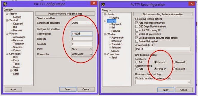
Step-6. Type “AT+GMR” follow by Ctrl-M Ctrl-J then hit Enter to check the firmware version.

Yeah!! Now we have a working ESP-03 that responds to AT command. In addition, the WiFi signal of the module can now be detected using a smartphone, tablet or a computer that supports WiFi.
Please feel free to share this article, but please include a link back to this page.
No comments:
Post a Comment