For this post, I will be creating the part for SBL2040CT. The datasheet of this part can be found at http://www.mouser.com/ds/2/115/diodes%20inc._ds23015-543535.pdf.

Creating the package for a new part.
1. Launch Eagle PCB.
2. Go to "Libraries".

3. Scroll down to find "ref-packages.lbr".

4. Find the right package for the part to be created.
For TO220AB, there are 2 available packages - TO220AB (horizontal) and TO220ABS (vertical). Since I want to mount the part vertically on my board, I pick TO220ABS as the reference package for my part.

5. Open the library that contain the reference package.
Now that we are certain that the needed package is in "ref-packages.lbr". Double left click on "ref-packages.lbr" to open the library editor.

6. Go to "Library" -> "Package..." to launch the window for selecting the package to be edit.

Scroll down the list to find the package to be edited.

Left click on "OK" to bring in the selected package.

7. Issue the "group" command.

Then press the left mount button and drag mouse to select the entire package.

8. Issue the "cut" command.

Move mouse to the origin point (cross hair point) of the package, right click to bring up the action menu and select "Cut: Group".

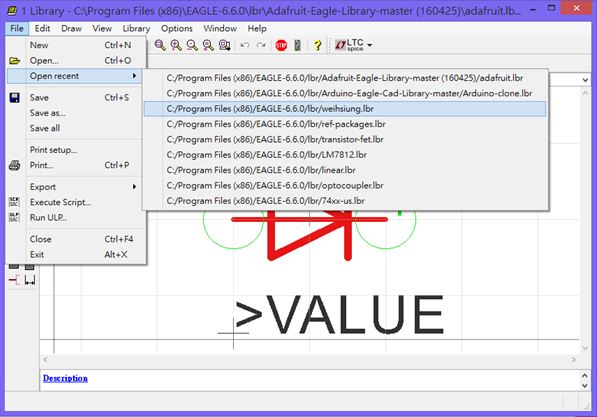
9. Open the library where the new part will be kept.
If the library is opened recently, go to "Open recent" to select the library.

If not, use "Open" to open the library. In my case, I want to put the new part in my private library "weihsiung.lbr".

Once there, go to "Library" -> "Package..." to launch the Edit window.

There is nothing in the Edit window (because I haven't created any part yet).

In the blank field next to "New:", type in the package name "TO220ABS" (it's the package name of the new part that will be created), left click on "Pac" to make sure we are creating a new package. Then click on "OK".

Click on "Yes".

To bring up the edit window.
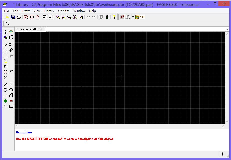
11. Issue the "paste" command to paste the reference package into the edit window.

The reference package of TO220ABS is now copied from "ref-packages.lbr" into "weihsiung.lbr".

IMPORTANT!!
Pay attention to where to put the origin point of the package (where the cross hair sign is). In the above sample, the origin point (cross hair sign) is on the upper center of the package.
12. Add description by click on the blue "Description" and enter the description.

Go to "File" -> "Save" to save the work.
That's it for creating the package for a new part. Next we will be working on the symbol of the new part.
Creating the symbol for a new part.
For SBL2040CT, below is the symbol on the datasheet.


For SBL2040CT, I think the Diode symbol in "adafruit.lbr" is quite good.

2. Double click on "adafruit.lbr" to open the edit window.
Once there, go to "Library" -> "Symbol".

And locate "DIODE" from the list.

3. Click "OK" to bring in the symbol for "DIODE".

4. Use the Group command to select and group the entire symbol.
5. Use the "Copy" -> "Copy: Group" command to copy the entire group.

6. Open the library that will keep the new part.
7. Once the library is opened, go to "Library" -> "Symbol".

Then enter "DIODE" and click "OK" to create a new symbol.

Click "Yes" to confirm the action.

8. Issue the paste command to paste the copied symbol.

IMPORTANT!!
Pay attention to where to put the origin point of the symbol (where the cross hair sign is). In the above sample, the origin point (cross hair sign) is on the center (inside the triangle) of the symbol.
9. Go to "File" -> "Save" to save the work.
Creating the device
1. Go to "Library" -> "Device".

Enter the name of the device to be created. In this case, the device name is "SBL2040CT".

Click "OK", then "Yes" to confirm the action.

The below window will appear.

2. Click ""New" to bring up the package selection window.

Select the package name "TO220ABS" and click "OK".

3. Issue the add command to add symbol.

Select the symbol to be added and click "OK"

The symbol is now added. Notice the mark in red circle means that the signal pins of the package are not connected to those of the symbol.

For "SBL2040CT", 2 diodes are needed for the symbol.

However, when using copy to make another diode symbol, the system gives out the Error message below.

Note,
When this error happens, select "Edit Symbol" to modify the symbol (see end of this post on how to modify the symbol).
4. Click "Connect" to launch the window for connecting the pins with the pads.

The pad names in red are manually added for clarification.

First, select the pin, then select the pad, then click "Connect" to create the connection. Repeat this process until all pins and pads are connected.

Click "OK" , then go to "File" -> "Save". This new part is ready to be used.
Below is how the new part looks in the schematic window and the board window.

--------------------------------------------------------------------------------------------------------------------------
Final touches
The texts of P$1, P$2, P$3, A1, C, and A2 make it hard to see the symbol clearly (the symbol for IRF9530 is much cleaner).

1. Right click on the symbol and select "Open Device" from the menu.


2. Right click on the symbol and select "Edit Symbol" from the menu.

3. Select "Info." from the list of icons on the left side and click on a pin to bring up its property window (note, be sure to select the pin not the wire).

4. Set "Visible" to off to hid the texts for both pad and pin.

Repeat step 3 and 4 to turn the visible setting for the 3 pins to off.

Go to "File" -> "Save" to save the change.
5. In schematic edit window, go to "Library" -> "Update" and select the library that contains the new device for update.

The symbol in the schematic edit window is now updated to the new one.

For info. on how to create a new part from scratch, see my other post at http://wei48221.blogspot.tw/2014/08/eagle-pcb-tutorial-creating-new-part_9.html.
Reference
CadSoft Eagle. Creating a new part from existing package and symbols.
https://youtu.be/e5zL3gUN4jw
No comments:
Post a Comment