Showing posts with label 433MHz. Show all posts

2016/08/24

How to use the UART of Raspberry Pi for wireless communication - part 2

This is a quick summary of how to connect Raspberry Pi to a 433MHz Serial to Wireless module (HC-11 / HC-12) and how to program the Pi using Python to receive incoming data.

Before the Pi's UART can be used for this purpose, there are some preparations that need to be made. Please refer to http://wei48221.blogspot.tw/2016/08/how-to-use-uart-of-raspberry-pi-for_99.html for info. on how to prepare the Pi's UART.

Schematic:


Checking the version of the installed Python.

Issue "python --version".


Install pySerial

Issue "sudo apt-get install python-serial".

Other preparation works

Create a folder call "python" (if it hasn't been created) to keep the python programs.

1. Issue "mkdir python" to create the python folder.

2. Issue "ls" to make sure the folder is created.


Change working directory to the newly created python folder.

"cd python"

Launch nano text editor and name the file created "serial_read.py"

"nano serial_read.py"

Code

Type in the code between the 2 dash lines.
----------------------------------------------------------------------------------------------------------------------
#!/usr/bin/env python

import time
import serial

ser = serial.Serial(
         port='/dev/ttyAMA0',
         baudrate = 9600,
         parity=serial.PARITY_NONE,
         stopbits=serial.STOPBITS_ONE,
         bytesize=serial.EIGHTBITS,
         timeout=1
         )
counter=0
   
while 1:
         x=ser.readline()
         print x
---------------------------------------------------------------------------------------------------------------------
IMPORTANT!!

Watch out for the indent as python uses spacing at the start of the line to determine when code blocks start and end (http://stackoverflow.com/questions/1016814/what-to-do-with-unexpected-indent-in-python).

Save the program.
Ctrl-X to exit the editing mode, then "Y" to save the file.

Running the program 

"python serial_read.py".

Here I have an Arduino Uno with some sensors and a HC-11 module attached to it. Whenever a sensor is triggered, the Uno will send a message out via the HC-11 module. The message is picked up by the "serial_read.py " running on the Raspberry Pi and displayed in the PuTTY terminal.


When we are done with the program, use Ctrl-C to stop its execution.

References:

Using UART on Raspberry Pi – Python
https://electrosome.com/uart-raspberry-pi-python/

Arduino Lesson 17. Email Sending Movement Detector
https://learn.adafruit.com/arduino-lesson-17-email-sending-movement-detector/python-code

Read and write from serial port with Raspberry Pi
http://www.instructables.com/id/Read-and-write-from-serial-port-with-Raspberry-Pi/

---------------------------------------------------------------------------------------------------------------------

Product Offered:

Note, the 2 modules listed here have been tested to work with Arduino Uno and Raspberry Pi.

433MHz Serial RF Module -- HC-11


- Price: US$6.99/ea;
- Item Location: Taipei, Taiwan;
- Range: ~100 Meters (direct line of sight without obstruction);
- Frequency: 433MHz;
- Operating Voltage: DC 3.3V ~ 5V (when feeding DC 3.3V to the VCC of the module, the module works with Raspberry Pi without the need for level shifting / voltage division);
- Serial baud rate: 1.2Kbps to 115.2Kbps (default 9.6Kbps);
- Interface protocol: UART/TTL;
- At least 2 HC-11 modules are needed to form a complete wireless link.

IMPORTANT - THIS MODULE DOESN'T WORK WITH THE 433MHz Serial RF Module HC-12.

-------------------------------------------------------------------------------------------------------------------------

433MHz Serial RF Module -- HC-12
- Price: US$7.99/ea;
- Item Location: Taipei, Taiwan;
- Range: ~1000 Meters (@ 5000bps) direct line of sight without obstruction);
- Frequency: 433MHz;
- Operating Voltage: DC 3.3V ~ 5V (when feeding DC 3.3V to the VCC of the module, the module works with Raspberry Pi without the need for level shifting / voltage division);
- Serial baud rate: 1.2Kbps to 115.2Kbps (default 9.6Kbps);
- Interface protocol: UART/TTL;
- At least 2 HC-12 modules are needed to form a complete wireless link.

IMPORTANT - THIS MODULE DOESN'T WORK WITH THE 433MHz Serial RF Module HC-11.

How to purchase:

Leave your message in the comment section below or send me an e-mail. I will contact you for detail.

2016/08/23

How to use the UART of Raspberry Pi for wireless communication - part 1

This post is the 1st part of a 2-part series on how to use the UART of Raspberry Pi for wireless communication.

This post is mainly about how to prepare the UART of Raspberry Pi. The Pi used is Raspberry Pi 1 Model B and the OS used is Raspbian Jessie.

For info. on the python environment, python serial, and the actual code, please refer to the post at http://wei48221.blogspot.tw/2016/08/how-to-use-uart-of-raspberry-pi-for_30.html.

Raspberry Pi 1 Model B


Raspberry Pi 1 Model B Specs.

Raspberry Pi 1 Model B Pin Map (from Sparkfun)


Step 1 - Check to see if the UART pins (GPIO 14 and 15) are configured as serial console which outputs all the kernel data during boot.

Issue the command "dmesg | grep tty" and observe the output.

The line with red underline indicates that the UART is configured as serial console.


Note, if you are using Pi model 3 do not use /dev/ttyAMA0 because it's assigned to bluetooth, use /dev/ttyS0 instead.

Step 2 - Free up the UART Pins (GPIO 14, 15)

Run the configuration command and follow the instructions below

sudo raspi-config

Select "9 Advanced Options".


Select "A7 Serial".


Select "No".


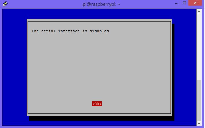
The serial interface is now disabled.


Select "<Finish>'.


Select <Yes> to reboot the system.


After the system is reboot, enter the command "dmesg | grep tty" to check whether the UART is no longer configured as serial console.

**IMPORTANT - for Raspbian Jessie - missing /dev/ttyAMA0**

When you disable the serial port for boot using raspi-config, the serial port is also disabled for ANY use. To fix this you MUST set "enable_uart=1" in /boot/config.txt.

This is really a bug in raspi-config.

/dev/ttyAMA0 is missing in the below output result after running "dmesg | grep tty" after system reboot.


Note, reference to this issue can be found at https://www.raspberrypi.org/forums/viewtopic.php?f=66&t=151922.

How to set "enable_uart=1" in /boot/config.txt

First, issue "sudo nano /boot/config.txt"

Second, scroll down to find the line "enable_uart=0".


Third, change it to "enable_uart=1", followed by pressing Ctrl-X, followed by pressing Y to save the change and exit the nano editor.


Fourth, issue the "sudo reboot" command to reboot the system.

Fifth, issue the "dmesg | grep tty" command to check for the presence of /dev/ttyAMA0.

From the output result below it's clear that ttyAMA0 is now available and we could move on to the next step.


Step 3 - Verify whether the Pi could send and receive UART data by installing the tool Minicom.

First, install Minicom.

sudo apt-get update
sudo apt-get install minicom

Second, short the Rx and Tx pins on Pi (GPIO 14 and 15) so that it will receive the same data as it transmits.


Third, launch Minicom by issuing the command "minicom -b 115200 -o -D /dev/ttyAMA0". Where, 115200 is the baud rate, ttyAMA0 is the port.


Press Ctrl-A, then Z to bring up the menu. Press E to enable or disable local echo.


When local echo is enabled, you will see 2 identical characters when pressing any key on the keyboard. This mean the UART is working correctly.


References:

Raspberry Pi Serial Communication: What, Why, and a Touch of How
https://jeffskinnerbox.wordpress.com/2012/12/05/raspberry-pi-serial-communication/

Raspberry GPIO
https://learn.sparkfun.com/tutorials/raspberry-gpio

Identifying Your Model of Raspberry Pi
https://www.element14.com/community/docs/DOC-78141/l/identifying-your-model-of-raspberry-pi

Read and write from serial port with Raspberry Pi
http://www.instructables.com/id/Read-and-write-from-serial-port-with-Raspberry-Pi/

Blog of Wolfgang Klenk
https://wolfgangklenk.wordpress.com/

Using UART on Raspberry Pi – Python <-- ***Good Read!!***
https://electrosome.com/uart-raspberry-pi-python/

Using the GPIO Serial port ttyAMA0
https://www.raspberrypi.org/forums/viewtopic.php?f=44&t=17360

Using the UART
http://www.raspberry-projects.com/pi/programming-in-c/uart-serial-port/using-the-uart

2016/06/07

Simple wireless instant messenger using Arduino + HC-11

This is a quick summary of a simple wireless instant messenger using Arduino + HC-11.

Wiring - Sender (Arduino Uno)


Wiring - Receiver (Arduino Nano)


Code - Sender

#include <SoftwareSerial.h>

SoftwareSerial mySerial(2, 3); //RX, TX

void setup() {
  Serial.begin(9600);
  mySerial.begin(9600);
}

void loop() {


  if (Serial.available() > 0){             //Read from serial monitor and send over HC-11
    String input = Serial.readString();
    mySerial.println(input);  
  }

  if(mySerial.available() > 1){        //Read from HC-11 and send to serial monitor
    String input = mySerial.readString();
    Serial.println(input);  
  }
  delay(5);
}

Code - Receiver

#include <SoftwareSerial.h>

SoftwareSerial mySerial(2, 3); //RX, TX

void setup() {
  Serial.begin(9600);
  mySerial.begin(9600);
}

void loop() {


  if (Serial.available() > 0){             //Read from serial monitor and send over HC-11
    String input = Serial.readString();
    mySerial.println(input);  
  }

  if(mySerial.available() > 1){        //Read from HC-11 and send to serial monitor
    String input = mySerial.readString();
    Serial.println(input);  
  }
  delay(5);
}

Reference

Long range, 1.8km, Arduino to Arduino wireless communication with the HC-12
https://www.youtube.com/watch?v=DGRPqeacJns

2016/06/05

Remotely control servo motor via wireless interface that supports link loss indication

This is a prototype for verifying the design to control a servo motor via a wireless interface that supports link loss indication.

Schematic

Master (Local)


Slave (Remote)


Source Code - Master (Local)

const int LED_Alive =  2;          // Alive indicator LED
const int LED_Error =  3;          // Error indicator LED

int state = 0;                  // state of output signal, 0 = "L", 1 = "H".
int incomingByte;               // a variable to read incoming serial data into

void setup() {
  Serial.begin(9600);
  pinMode(LED_Alive, OUTPUT);
}

void loop() {

long interval = 300000; // 1 second?
int ok = 0;             // 0 = reply not ok, 1 = reply ok.

// switch the output status
  if (state == 0) {
    state = 1;
  } else {
    state = 0;
  }

  if (state == 1) {
    Serial.print("H");      // Send "H"
    digitalWrite(LED_Alive, HIGH);  
  } else {
    Serial.print("L");      // Send "L"
    digitalWrite(LED_Alive, LOW);
  }

  // Listen to reply from remote site for 1 second

  while (interval >= 0) {
    if (Serial.available() > 0) {
      incomingByte = Serial.read();
      //Serial.print(incomingByte);
      //break;            // break from the while loop
    }
    interval = interval - 1;      
  }

  switch (incomingByte) {
    case 72:                              // "H"
        if (state == 1) ok = 1;           // Send "H", receive "H".
      break;
    case 76:                              // "L"
      if (state == 0) ok = 1;             // Send "L", receive "L".
      break;
    default:
      ok = 0;                             // if nothing else matches, do the default
    break;
  }

  if (ok == 0)
   digitalWrite(LED_Error, HIGH);         // Turn on the error indicator
  else
   digitalWrite(LED_Error, LOW);          // Turn off the error indicator
}

Source Code - Slave (Remote)

#include <Servo.h>

Servo myservo;  // create servo object to control a servo
                // a maximum of eight servo objects can be created
int pos = 0;    // variable to store the servo position

const int ledPin = 13; // the pin that the LED is attached to
int incomingByte;      // a variable to read incoming serial data into

void setup() {
  // initialize serial communication:
  Serial.begin(9600);
  // initialize the LED pin as an output:
  pinMode(ledPin, OUTPUT);

  myservo.attach(A0);  // attaches the servo on pin 0 to the servo object
}

void loop() {
  // see if there's incoming serial data:
  if (Serial.available() > 0) {
    // read the oldest byte in the serial buffer:
    incomingByte = Serial.read();
    // if it's a capital H (ASCII 72), turn on the LED:
    if (incomingByte == 'H') {
      Serial.print("H");                // send reply back to remote site
      digitalWrite(ledPin, HIGH);
      myservo.write(180);              // tell servo to go to position 180
    }
    // if it's an L (ASCII 76) turn off the LED:
    if (incomingByte == 'L') {
      Serial.print("L");
      digitalWrite(ledPin, LOW);
      myservo.write(0);              // tell servo to go to position 0
    }
  }
}

Note,

There seems to be a problem with the serial interface of the Arduino Nano used for this project. If the Nano is powered off (unplug the USB from the computer) then powered on (plug the USB cable back to the computer) while the above program is running, the Nano won't be able to send feedback to the Master device (the Link Loss Indicator on the Master device will keep flashing). When this happens, launching the Serial Monitor on the computer attaching to the Nano or re-uploading the program to the Nano could solve this problem. However, this problem doesn't exist if the Nano is replaced with Uno.