OS used: Windows 8.1
Compile the NodeMCU firmware
This site - https://nodemcu-build.com/index.php is very helpful for building customized NodeMCU firmware. If you find it useful, please make some donation to reward the author and to keep the site running.
For this post, below is the configuration used for making the NodeMCU firmware.


Save the compiled NodeMCU firmware
Two e-mails will be sent to you. The first one tells you that the firmware is being compiled. The second one tells you where to download the firmware and other info.
Depending on how busy the server is, the interval between the 1st and the 2nd e-mail is around 5 ~ 10 minutes.

Right click on the link to save the firmware to a directory for later use.
Wire up ESP-01 to CP-2102

Write firmware to ESP-01
1. Download "nodemcu-pyflasher" from https://github.com/marcelstoer/nodemcu-pyflasher. Unzip the downloaded file to a directory.
2. Launch Command Prompt.
3. Change the working directory to where the unzipped files are stored. Issue "python nodemcu-pyflasher.py" to run nodemcu-pyflasher.

4. Select the serial port to be used and the firmware to be written into the on-board flash memory of ESP-01. Set the other settings as shown below.

5. Be sure to do the following before clicking on the "Flash NodeMCU" buton.
- Provide external +3.3V to ESP-01 (make sure the +3.3V is connected to VCC, and the GND is connected to GND);
- Plug the CP-2102 module to the USB port of the computer used for firmware upload;
- First close the flash switch then the reset switch so that both GPIO0 and RST of ESP-01 are connected to GND;
- First open the reset switch then the flash switch so that bboth GPIO0 and RST are floating;
- Click on the "Flash NodeMCU" buton.
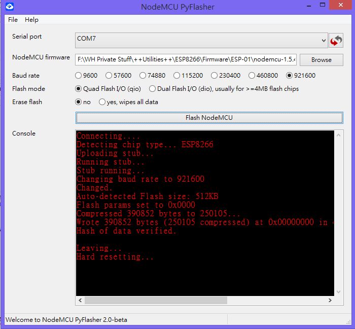
The firmware is now written into the on-board flash memory of ESP-01.
Verify the written firmware
1. Download ESPlorer from https://esp8266.ru/esplorer/. Unzip the downloaded file and save the unzipped files in a directory.
2. Follow the schematic below to wire up ESP-01 to the USB to TTL Module. Basically, it's the same as the one shown earlier in this post, except that GPIO0 is now free up.

3. Move to the directory where ESPlorer.jar is located. Double left click on it to launch it.

4. Observe the settings (COM Port, Baud Rate, AutoScroll) in the photo below.

5. Follow the procedure below for ESPlorer to connect to ESP-01.
- Close the reset switch so that it's connected to GND.
- Left click on the "Open" button.
- Open the reset switch so that it's in floating state.
There will be some random symbols showing in the window on the right.

- Left click on the Reload button.

- Left click on the Reload button again.
ESPlorer can now correctly communicate with ESP-01.

6. Get the sample Lua code from the link below.
https://gist.githubusercontent.com/RuiSantosdotme/6048a62eaf58a0e70ea8/raw/b1ecbeb9f42af7673ef8ab0af8d4e1604e7df1aa/init.lua
1 2 3 4 5 6 7 8 9 10 11 12 | lighton=0 pin=4 gpio.mode(pin,gpio.OUTPUT) tmr.alarm(1,2000,1,function() if lighton==0 then lighton=1 gpio.write(pin,gpio.HIGH) else lighton=0 gpio.write(pin,gpio.LOW) end end) |
Below is the schematic for the sample code above.

7. Left click on the Open button and enter init.lua to create a new file call "init.lua".

8. Copy and paste the sample code to the left window in ESPlorer.

9. Left click on the "Save to ESP" button. The saved content will be displayed in the window on the right.

Note: To delete the saved "init.lua" file, simply type in "file.remove("init.lua")" and press the "Send" button (see figure below). Or, type in the command "file.format()" to remove all the files saved in ESP-01. You could type any commands and send them to ESP-01 through that window.

The Result
Note that the 3.3V needed to power the below demo is supplied by CP-2102, not the external power supply. It's not sure whether the 3.3V from CP-2102 is enough for flashing the NodeMCU firmware but it's enough to drive the LED after the firmware is written into the on-board flash memory.
References:
ESP8266 ESP-01 Webserver
https://www.hackster.io/ROBINTHOMAS/esp8266-esp-01-webserver-7248ca
ESP-01 Pinout Diagram Cheat Sheet
http://adlerweb.deviantart.com/art/ESP8266-ESP-01-Module-Pinout-Diagram-Cheat-Sheet-575950438

ESP8266-01 Building Blocks: Unleash 2 Bonus GPIO Pins
http://www.instructables.com/id/ESP8266-01-Building-Blocks-Unleash-2-Bonus-GPIO-Pi/
No comments:
Post a Comment