First of all, let's see the DRC results using design rules from adafruit and sparkfun respectively.
DRC Results
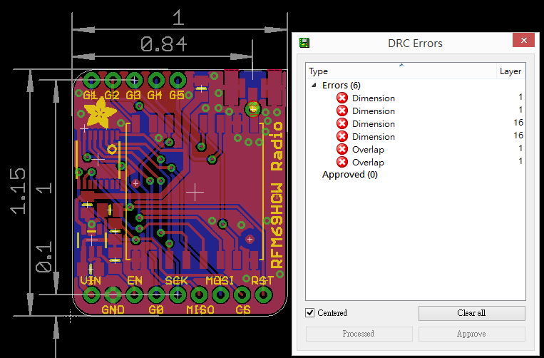
Using "adafruit.dru"

Using "sparkfun.dru"

The settings of "adafruit.dru" and "sparkfun.dru"
Layers

Clearance

Distance

Sizes

Resting

Shapes

Supply

Masks

Misc

For board manufacturing, I mainly use PCBWay. The PCB manufacturing capabilities of PCBWay are listed at https://www.pcbway.com/capabilities.html.
The table below was taken from the "PCB Capabilities - Quick-turn PCB" section from the link above and added with the design rules of adafruit and sparkfun and my personal notes.

Changing and testing the design rules
From the table above, it's clear that the Drill Sizes setting (see the part in red box below ) in "sparkfun.dru" could be loosened to the same as that in adafruit.dru.

Follow the steps below to change the minimum drill setting from 20mil to 16mil.
1. Load the schematic and gerber of the board design;
2. Launch DRC;
3. Load "sparkfun.dru";
4. Click "Sizes". Change the Minimum Drill setting from 20mil to 16mil as shown below;

5. Click "Apply", then click "Check" to perform DRC;
6. From the result generated, it's clear that there is no longer any drill size error;

7. However, there are still more errors (clearance error x 3) than the DRC result generated by using adafruit.dru (see below pic).
To solve this problem, follow the steps below:
1. Click on any one of the Clearance error in the DRC Errors window to find the location of the error. From the pic below, it's clear that the cause has something to do with via.

2. Launch DRC, click on "Resting" then change the Outer and Inner settings for Vias from 10mil to 8mil as shown below.

3. Click "Apply", then click "Check" to perform DRC again;

The numbers and types of error are the same as those checked by using "adafruit.dru" now. From the data highlighted in the red square in the table below, it's clear that the change is within the allowable range of PCBWay.

No comments:
Post a Comment