DEVO 7E Transmitter and RX601 Receiver

3-wire Servo
How it works?
An Arduino Uno board is used to take in the PWM signals from the PWM outputs of the receiver. The PWM signals are then processed by the software running on the Arduino Uno board to come out with the control signals to be fed to the computer connected to the Arduino Uno board via a USB cable. The computer treats the input signals as from a connected joystick and the signals are used to control the games / simulators running on the computer.
The PWM waveforms
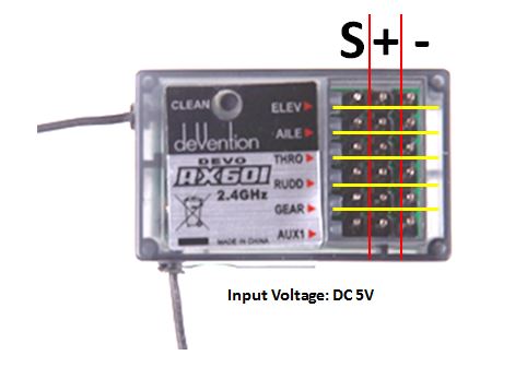
Before a program can be made to process the PWM signals, we need to know how they look. The photo below shows the division of the channels on the RX601 receiver.

The waveform of the PWM output of each channel on the receiver are shown below.

The waveform of the PWM output of each channel on the receiver are shown below.


Code
int tmp;
unsigned long time_now;
void setup(){
setupPins();
setupUnoJoy();
}
void loop(){
// Always be getting fresh data
dataForController_t controllerData = getControllerData();
setControllerData(controllerData);
}
void setupPins(void){
// Set all the digital pins as inputs
// with the pull-up enabled, except for the
// two serial line pins
for (int i = 2; i <= 12; i++){
pinMode(i, INPUT);
digitalWrite(i, HIGH);
}
pinMode(A4, INPUT);
digitalWrite(A4, HIGH);
pinMode(A5, INPUT);
digitalWrite(A5, HIGH);
// RX601 Receiver CH1 Input,
pinMode(A0, INPUT);
}
dataForController_t getControllerData(void){
// Set up a place for our controller data
// Use the getBlankDataForController() function, since
// just declaring a fresh dataForController_t tends
// to get you one filled with junk from other, random
// values that were in those memory locations before
dataForController_t controllerData = getBlankDataForController();
// Since our buttons are all held high and
// pulled low when pressed, we use the "!"
// operator to invert the readings from the pins
// The section below is not used in our application.
//---------------------------------------------------------------
controllerData.triangleOn = !digitalRead(2);
controllerData.circleOn = !digitalRead(3);
controllerData.squareOn = !digitalRead(4);
controllerData.crossOn = !digitalRead(5);
controllerData.dpadUpOn = !digitalRead(6);
controllerData.dpadDownOn = !digitalRead(7);
controllerData.dpadLeftOn = !digitalRead(8);
controllerData.dpadRightOn = !digitalRead(9);
controllerData.l1On = !digitalRead(10);
controllerData.r1On = !digitalRead(11);
controllerData.selectOn = !digitalRead(12);
controllerData.startOn = !digitalRead(A4);
controllerData.homeOn = !digitalRead(A5);
//--------------------------------------------------------------
// Get the input from CH1 of RX601
while (digitalRead(A0) == LOW) {}
time_now = micros();
while (digitalRead(A0) == HIGH) {}
tmp = micros() - time_now;
controllerData.leftStickX = tmp >> 2;
//Serial.println(tmp);
while (digitalRead(A1) == LOW) {}
time_now = micros();
while (digitalRead(A1) == HIGH) {}
tmp = micros() - time_now;
controllerData.leftStickY = tmp >> 2;
//Serial.println(tmp);
while (digitalRead(A2) == LOW) {}
time_now = micros();
while (digitalRead(A2) == HIGH) {}
tmp = micros() - time_now;
controllerData.rightStickX = tmp >> 2;
//Serial.println(tmp);
while (digitalRead(A3) == LOW) {}
time_now = micros();
while (digitalRead(A3) == HIGH) {}
tmp = micros() - time_now;
controllerData.rightStickY = tmp >> 2;
//Serial.println(tmp);
// And return the data!
return controllerData;
}

For more about how to prepare Arduino Uno for the above application, please refer to the posts mentioned in the reference section below.
References
How to use Unojoy with Arduino Uno
How to turn Arduino Uno into HID Keyboard - Part 2 of 2
How to turn Arduino Uno into HID Keyboard - Part 1 of 2
http://wei48221.blogspot.tw/2016/06/arduino-uno-hid-keyboard-joystick-part.html
---------------------------------------------------------------------------------------------------------------------
Buying Info.
I've prepared a kit that contains one Arduino Uno board pre-configured and pre-loaded with the necessary software and accessories (see below photos for the included items). Please e-mail me if you want to order or have any questions.
Price: US$30 per kit;
Shipping: Free shipping for order over US$50 to most major countries (please contact me to see if free shipping is applicable to your location);
Tax and tariffs: To be paid by the buyer;
Item location: Taipei, Taiwan;
Items included:
- 1 x Arduino Uno board;
- 1 x USB cable;
- 6 x Jumping wires with connectors.

The photo below shows how to connect the RX601 with the Arduino Uno board.

---------------------------------------------------------------------------------------------------------------------
Buying Info.
I've prepared a kit that contains one Arduino Uno board pre-configured and pre-loaded with the necessary software and accessories (see below photos for the included items). Please e-mail me if you want to order or have any questions.
Price: US$30 per kit;
Shipping: Free shipping for order over US$50 to most major countries (please contact me to see if free shipping is applicable to your location);
Tax and tariffs: To be paid by the buyer;
Item location: Taipei, Taiwan;
Items included:
- 1 x Arduino Uno board;
- 1 x USB cable;
- 6 x Jumping wires with connectors.

The photo below shows how to connect the RX601 with the Arduino Uno board.