To make it easier to pack the machine and move, I've made some modifications to my 8" Prusa i3 and made a kit for those who are interested in owning one.
The print area of the machine is around 20cm x 20cm x 18cm (7.87" x 7.87" x 7.08").
This post provides instructions on how to assemble the mechanical parts of the printer. A separate post will be dedicated to the assembly of the electrical parts.
Overview
The kit consists of the following parts:
1. Pre-assembled Z frame assembly and Y frame assembly including motors and end stops.
2. Pre-assembled gear extruder.

3. Pre-assemble hotend (J-Head or All Metal)
By default, the filament diameter is 3mm, The nozzle diameter is 0.4mm.


4. Electronics

Note, depending on the option ordered, the LCD module and its accessories (cable (top) and adapter board (top right)) may not be included in the kit.
5. Power Supply (Input: AC110 ~ 220V, Output: DC 12V, 30A)

A ceramic screwdriver similar to the one below is provided for adjusting the stepper driver trimpots.

Note, the following tools / items are not provided with the kit but are needed for the assembly:
- Phillips screwdrivers
- Hex key wrenches
- Electrician wire pliers
- Diagonal cutter
- Soldering iron, solder paste, and soldering wire.
- 18 AWG electrical wire
Frame Assembly
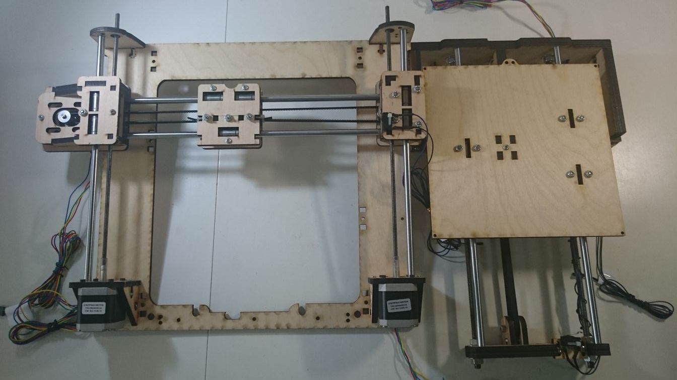
1. Put the Y frame assembly into the Z frame assembly like the photo below.

Fasten the screws and washers on the Y frame threaded rods.

2. Remove the top panel from the Z frame assembly and mount the 2 side panels to the back of the Z frame assembly.

Put the top panel back after the 2 side panels are in place and secure them with screws and bolts.


3. Secure the Y frame assembly to the Z frame assembly and the 2 side panels with screws and bolts.


The Y frame assembly is securely fixed to the Z frame assembly and the 2 side panels with 5 screws and bolts.

4. Secure the 2 vertical smooth rods of the Z frame with covers.


Gear Extruder Assembly
1. Mount the extruder mounting plate and its 2 side panels to the X carriage.
X carriage.

X carriage with extruder mounting plate and 2 side panels installed.

Side panel for mouting the X endstop probe.

X endstop probe.

Side panel for mounting a SG90 servo for auto bed leveling.

2. Mounting the gear extruder assembly and the hotend.

Here, an all metal hotend is used as an example. Other types of hotend (J-Head, E3D, etc.) can be used as well.

Attach the top of the hotend to the bottom of the extruder to form the extruder and hotend assembly.

The extruder and hotend assembly is secured to the extruder mounting plate with 2 screws screwing in from the bottom of the extruder mounting plate.

Important!!
Make sure there is enough space for the gear on the extruder to rotate freely before fastening the screws to secure the extruder and hotend assembly to the extruder mounting plate.
Slide the extruder and hotend assembly forward to create space when needed.

3. Mounting the motor
Put a small gear onto the shaft of the motor and mount the motor to the extruder with 3 screws.
Important!!
Before fastening the 3 screws to secure the motor position, make sure the 2 gears are against each other and can rotate smoothly (not too tight, not to loose).

Front view of the finished extruder and hotend assembly with motor mounted. The two long screws in the center of the extruder are for mouting the cooling fan.

Extruder with cooling fan.

Mounting the Heated Bed
1. Insert the screws

From bottom to top: screw, wood, bolt, spring.

2. Place the heated bed on top of the wooden platform and secure the bed with bolts.

Mounting the LCD Module
Note, depending on the option ordered, the LCD module and its accessories may not be included in the kit.

It’s easier to fasten the side panel to the front panel by screw in the bolt into the side panel first then slide the bolt into its place on the front panel.


Filament Insertion
1. Remove one of the screws to loosen the roller base.

2. Insert filament, put back the removed screw, adjust the tension of the roller against the filament by tightening or loosening the 2 bolts.

O.K. That's all for the assembly of the mechanical parts. Congratulations!! :-)
P.S. About Auto Bed Leveling
When using the Auto Bed Leveling feature, DO NOT issue command that changes the position of X, Y, or Z after G28 (Homing) and G29 (Probing) are executed. Doing so will cause the system to lose the data gathered from executing the Auto Bed Leveling command.
P.S. About Auto Bed Leveling
When using the Auto Bed Leveling feature, DO NOT issue command that changes the position of X, Y, or Z after G28 (Homing) and G29 (Probing) are executed. Doing so will cause the system to lose the data gathered from executing the Auto Bed Leveling command.
i am just amazed the way you took the pictures for laser cutting and the main process and highlight you have picked from it.metal sheet fabrication are now utilized in multiple places and industries to design stylish products.
ReplyDelete