Wiring Diagram
First, wire up the DUT (LM2596 Board) and the rest of the equipment according to the below diagram.

Block out DC component of the input signal
1. Power up the scope.

2. Press the CH1 button (assuming CH1 will be used for the measurement).
The menu shows that DC Coupling is enabled.
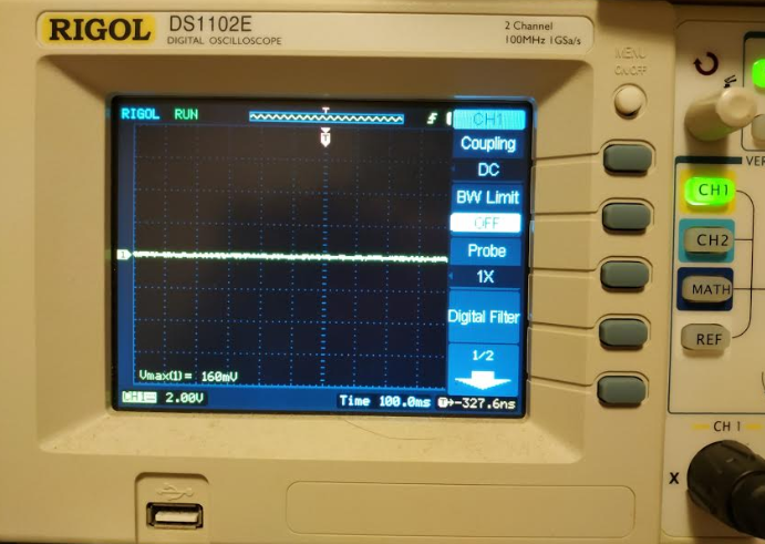
3. Press the button next to Coupling DC to bring up the next level menu.

4. Rotate the knob counter-clockwise to select "AC".

Press the knob to confirm the selection.

5. AC Coupling is now enabled for CH1.

Set Bandwidth Limit (BW Limit)
Press the button next to BW Limit OFF.

BW Limit is now ON.

According to page 2-2 of the RIGOL User's Guide that can be found here, setting BW Limit to "ON" limits the channel bandwidth to 20MHz which could reduce the display noise.

Measuring the ripple
1. Be sure the DUT and the equipment have all been connected properly and supplied with power.
2. At first glance, there is nothing on the scope (because the DC component has been filtered out).

3. Rotate the Vertical knob to set the vertical scale to 50.0mv.
Below is the ripple (around 30mV) measured before adding any load to the output of the DUT.

4. Below is the ripple (around 70mV) measured after a 0.2A load is added to the DUT's output.

5. Below is the ripple (around 184mV) measured after a 2A load is added to the DUT's output.

Conclusion
According to the LM2596 datasheet, the maximum output ripple is around 100mV.

It seems my first attempt at doing switching power supply is not so successful because the output noise is much higher than 100mV. I need to find a different regulator that has lower output noise and follow the datasheet's component selection recommendation and layout techniques such as the one below closely.
Basic Switching-Regulator-Layout Techniques
https://pdfserv.maximintegrated.com/en/an/AN2997.pdf
Reference:
EEVblog #594 - How To Measure Power Supply Ripple & Noise
https://www.youtube.com/watch?v=Edel3eduRj4
Switching Regulators and Switching Noise
https://chrisgammell.com/switching-regulators-and-switching-noise/
========================================================================
Testing the ripple of OKI-78SR
For comparison, I obtained one OKI-78SR-3.3/1.5-W36-C and one OKI-78SR-5/1.5-W36-C for testing. The datasheet of the 2 modules can be found at the link below:
https://www.murata.com/products/productdata/8807037992990/oki-78sr.pdf?1583754815000
The test setup and the test results are shown below.
Test Setup
The DUT on the left is OKI-78SR-5/1.5-W36-C. The meter in the center shows the voltage and the current of the output from the DUT and the electronic load on the right serves as the load that draws power from the DUT.

The Results
The range of the ripple measured is between 14mV and 31mV.

According to the OKI-78SR datasheet, the typical/normal ripple is around 30mV and the maximum is around 40mV. The test results are in line with these 2 figures.

No comments:
Post a Comment